GIG reference manual
nurbs tutorial
____________________________________________________________________________________
Tutorials
In this exercise you will learn how to start the nurbs modeler and see how the
user interface has been set up.
- Start the nurbs modeler by selecting nurbs from the tools menu in GIG. You
can also start the nurbs modeler directly from a UNIX window. You will have to be
logged in as "GIG" and then type in the following command (note the uppercase
N):
- startNurbs <enter>
- The screen you see is the nurbs modeler display. It shows three camera windows:
the contour view in the left window, the spine view in the upper right window,
and the model view showing the swing model created from these curves in the
lower right window.
- The yellow buttons on the right are used to control the camera. The functions
here are applied to the selected camera. Select a camera by clicking in its window which is indicated as being active by
displaying a red border.
- Left of the camera buttons are three important buttons: reset undo, undo, iso lines. These buttons control
the Nurbs feature and the Nurbs display mode. You can undo as many as 20
editing steps by pressing the undo button repeatedly. To undo an undo action,
first press reset undo and then undo. With the display mode button you can step
through a number of Nurbs display modes. Select the representation you like
best for the task at hand.
- The buttons on the very left side of the window, labeled Nurbs mode, points,
primitive, and animation are the main menu buttons. Use these buttons to select a set of
accessible functions concerned with general functionality (Nurbs mode), the
transformation of curve points (points), the modification of complete curves or curve segments (primitive), or the animation of your Nurbs models (animation).
- All menu function buttons update with selections made from the main menu
buttons. The default start up menu displays the Nurbs mode.


In this exercise you will learn how to create and modify curves.
With the GIG nurbs modeler 3D objects are constructed from curves. In this exercise you will create a rotational body and modify its curve by transforming and inserting control points.
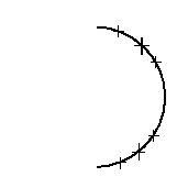
- In the Nurbs mode menu, select make swing. In the contour window you will see a half circle. This is the profile to be rotated along the path displayed in the upper right window (by default a circle). The result, shown in the model window, is then a sphere.
- Begin by viewing the actual object.
Select the model window by clicking in it.
Select the rotate cam button.
Press the middle mouse button and move the mouse to view the rotation of the object.
Press the left button to accept the given rotation (there is a reset button to
return the camera to a default setting) or the right button to cancel.
- Select the flat shaded button to view the object in a shaded view (not
available on all workstations).
Repeat rotation with rotate cam.
After you have accepted or cancelled the camera rotation, select the spine window by
clicking in it.
- Now, select the points menu to modify the rotational profile. Switch off flat shading in the camera menu if you like.
The points menu contains all the functions needed to modify a given curve. You
may add control points or delete them, and the standard transformations (move, rotate, etc.) are available to modify the curve shape. Furthermore, you may select points or a set of points and you can define grids.
- Select the model window, then select grid and show grid. Click on the xy, xz, and yz grids.
In the model window use rotate cam in order to view the object within the 3d
xyz planes.
- Press transform when you have finished with the grid to return to the point mode.
- One of the versatile features of Nurbs is that you can add control
points wherever you want without changing the curve shape, thereby allowing significant surface editing possibilities.
Select the contour window.
To add CPs (control points) select the add points button.
Now, by clicking on the control polygon of the contour you can add control
points to the curve. After inserting a point, a special cursor shape appears,
denoting that the point can be moved before adding more points (by moving the mouse while keeping the middle mouse button pressed).
Note that the curve shape will not change unless you move the newly inserted control point.
- If you want to change the position of any existing CP, just press the move
button or any other transformation function and select the point you want to move. Note how the model shape will change according to the transformation.
To produce sharp corners, simply place two CPs on top of each other. To do it
precisely, use snap to.
You may also select multiple points. Use set to select a set of points; if you
expect to reuse the selection, you may give a name to the selected set by using tag points.
With move (or other transformation) selected, by clicking on the control
polygon, the entire curve will be selected and may be transformed.
All other transformations work exactly the same way. Note that there is a local co-ordinate system that can be positioned arbitrarily. This is especially useful for performing rotations.
Note also that if you click on a grid line, the grid will be selected for
transformation.
- Now we are going to add some points to the end of the curve.
Move one of the end points of the half circle (or what is left of it after your
editing experiments) away from the center line of the grid, the y-axis.
Now, select add points.
Click near the end point of the contour.
A new point can be added and moved. The old endpoint moves to the
position where you clicked.
Points can easily be deleted with the del points function.
- There is another parameter you should learn to use: the weight. As described in
the introduction, a spline resembles a piece of wood held into shape by
attached weights. The weight parameter now changes the mass of the weight
represented by a selected control point.
- Select the weight button and click on a CP.
By moving the mouse right or left while pressing the middle mouse button, you
can draw the curve nearer to the CP or further away. Note the cursor
shape: in the nurbs modeler, it always shows you the possible movement
directions for the mouse.
- At this time you have tried the most important simple curve manipulation commands.
Now we are going to design a Nurbs shape and import it into GIG.
Select the Nurbs mode.
Press save model.
Enter a name in the selection box and press confirm.
- Press the exit button and confirm by typing "y". If you started the Nurbs
modeler from the tools menu, you will now be in GIG, otherwise start the GIG program
by typing in:
- startgig <enter>
In GIG, go to the solid construct menu.
Select import nurbs.
Select your model.
Now the Nurbs model can be further modeled, be given attributes, rendered
and/or animated.
In this exercise you will learn how to create
more complex curves using advanced techniques such as splitting curves, intersecting and combining multiple curves, as well as other techniques.
This exercise consists of 4 parts:
The curve degree
The "degree" of a spline curve is a measure for the "roundness" of a curve. A
curve of the lowest possible degree will not be smooth but will be cornered like a
polyline. The higher a degree is raised, the "rounder" the shape.
- Start the nurbs modeler and create a default Swing.
- Select the model window and activate flat shaded.
- Select the rotational spine window (upper right).
Switch to the primitive menu.
- Press the lower button.
- Click on the rotational spine curve, which will change to a square. Look
at the model: it is now a half circle rotated along a square path.
- Press the raise button.
Click on the spine and watch it and the model change. Note that the curve does
not return to its previous shape.
Try more raising and lowering operations.
Creating a new curve
- Go to the Nurbs mode menu and select make swing.
Go to the primitive.
- Select delete and click on the contour curve in the contour window. The curve
will be deleted.
Go to the points menu.
- Select make curve.
- Click in the window with three points roughly in a horizontal line. Keep
the points to the right of the y-axis .
- Select add points to add more points to the curve.
- Select make curve again and create a second curve as displayed below.

Combining Curves
There are now two curves on screen that can be connected to create
one curve. Combining curves is very important in creating Nurbs surfaces to
be used as solids. If a Nurbs object has been composed by combining various unconnected
surfaces, it will be hollow, as if made of paper. If all splines are
connected and/or all curves are closed, the surface will be treated as a
massive solid. Combining curves is a powerful editing technique, as
predefined shapes can easily be connected to produce more complex shapes.
The GIG Nurbs Modeller provides two connecting techniques: smooth and linear
connections. A smooth connection connects two lines with a smooth spline curve;
a linear connection just creates a straight spline segment like a line
connection.
Note: Connecting segments with CPs very close together should be done with
straight segments because a smooth connection may result in a self-intersecting
curve, which is usually undesirable.
- Select connect in the primitive.
Click on one of the curves near the desired endpoint, then on the other.
Note: The help on-line data box, at the bottom of the screen, gives step-by-step instructions.
A straight connection spline segment will appear.
- Click on the linear connect toggle button. It will now read smooth connect.
- Click on connect again and select the two curves.
- A curved connection will appear.

Splitting and Intersecting Curves
This section describes another basic editing technique.
- Select Nurbs mode and create a default swing.
- Now, go to the primitive menu.
Select split.
Click on the half circle in the contour window at any position. You will see
new control points appear. The half circle is now cut into two parts.
- Click at another position somewhere below or above.
- Select delete.
Click on the curve segment between the two split points and it will disappear. You
have cut the curve into three sections and deleted one of them.

- Create a new curve using make curve from the points menu.
Select new curve again and create a second curve as displayed below.

- Go back to the primitive
and select intersect.
Click on the two curves, one after the other, near the intersection point. A
new CP appears at the intersection. Repeat this procedure for the 2 bottom
curves.
Delete the segments to create a curve as displayed below.

- Connect the intersected curves by clicking on the curves near the intersected
point. Then connect the top and bottom curve. Try the effect of connect
linear/smooth.
- Select Nurbs mode and edit surface to view the full model in the larger model
window.
This exercise uses the power of make swing to create a real-world object, a bathtub. A
bathtub generally is more or less oval, with one end being more flattened than the other. Below is a
cross section of the tub, as seen when the bathtub is cut in half.

- Create the shape drawn here from the default half circle in the contour
window. Try to use the add change button; when adding points at the end points of the curve, the original shape will not be maintained.
The resulting object, viewed in the model window, does not look like a bathtub
at all, but rather resembles a whirlpool.
- To further edit the object, select the spine window (upper right window).
- Select grid in the points menu. For the x, y and z grid units, select 0.125. Switch on snap to grid and the x and z boxes. Also switch on show grid and the xz box. Now the circle in the default spine window (upper right) must be modified.
The oval shape can be created by cutting the circle into two halves, moving
them apart and then connecting them in linear mode.
- To make the cut, switch to primitive and select split. Now click on the upper
section and split it by placing two points on each side of the oval. Use
delete to remove the smaller middle point. Repeat the process for the bottom
section.


The curve will now be split into two halves, one being black (the still active
rotational spine) and one being inactive. The model window shows that
only one half of the curve is used.
- Now, select the points menu and move. Click on each of control polygons of the circle halves and move them apart (control polygons may be difficult to see as they align with the grid).
- Now all that needs to be done is to switch to the primitive and
select the connect function, choosing connect linear.
The model window now shows a symmetrical bathtub. Look at it from different
angles using rotate cam. Switch the shading option on and off .

- Switch to Nurbs mode menu to save the model so that the bathtub can be
further edited, assigned attributes, rendered, and/or animated in GIG.
- To refine the bathtub using edit surface:
Use edit surface mode to do global changes to the model assembled from the
curves. In edit surface mode, each control point of the generated surface is
available to be modified in 3D.
- Note: All changes made in edit surface are removed when you deactivate edit surface, e.g., to change the construction curves.
- Switch to Nurbs mode menu.
Select edit surface. Now click on the control polygon of the bathtub. The
display changes, showing three different model views with the CP grid
superimposed in the three windows.
Try out the camera controls in all windows. You can put the desired view in the
large window by cycling through the cameras (by clicking the xy, xz, or yz text at the top right of the window) and using a combination of rotate cam, move, and zoom. It
may be useful to switch to flat cam (nonperspective camera for more precise
editing).
- Switch to points menu.
Select move to pick and displace CPs to deform the model. Be sure to undo
all deformations. (Remember that you can always terminate each transformation
with the right mouse button to cancel its effect.)
Try multiple selects with the set button for other deformations.
- Press the clear all button to clear all points that may be still selected.
Switch off the auto clear mode by pressing the appropriate button. This will
ensure that selected points will not be deselected automatically after the first
edit takes place.
- Cycle the large camera window to a side view. The other two windows show a
top and front view respectively.
- Now, set all the CPs on the right side of the object. Make sure that
only the outermost points are selected.
- Select the weight button and click on one of the selected points. The cursor
changes into a double pointed arrow.
Move the mouse to the right while pressing the middle button to add weight. As
you can see, the shape of the Nurbs surface is drawn towards the control
points, in effect creating a more rectangular shape of the right bathtub
outside. If you have selected the CPs carefully, the shape of the inner
profile, i.e., the basin shape, remains unchanged.
- Select the Nurbs mode and save model to import it into GIG.
This exercise makes use of make sweep to model surfaces.
- Select the Nurbs mode menu and select make sweep.
In the contour window you will see the default sweep contour, a simple flat line. In the spine window you will see two lines resembling the contour
(drawn as a horizontal line) and the spine itself (drawn as the vertical line
with CPs). The model window shows the result, in this case a simple
rectangular patch. If you create a patch by extruding a straight line along a
straight path, this is what you should expect.
- To modifying the spine,
click on the spine window to activate it.
Go to points menu.
Make sure the auto clear button is activated.
- Select move and move the lower and upper spine points to change the shape.
See how the model shape changes when you move control points. The shape of the
spine determines the shape of the extrusion: the spine is the line which the
straight contour line is extruded along.
- Select nurbs and edit surface.
Select rotate cam to view the object in the model view window.
- With scale and twist curves,
the GIG nurbs modeler can add more complexity to your extrusion models.
In the primitive menu, controls are available to edit scale and
edit twist curves. The idea is that the size of the extruded contour can be
modified by yet another curve defining the scale of the extrusion. With another
curve, the orientation perpendicular to the spine curve can be defined, in
effect creating "twists", or drill-like shapes.
Go to Nurbs mode menu.
Select make sweep.
- Switch to primitive and select edit scale. The defcurve window now
displays the scale curve instead of the extruded contour. The distance of the
scale curve (line) from the y-axis has a scale factor of 1. If you move part
of the curve nearer to the y-axis (the middle line), the corresponding
section of the extrusion will be scaled down; if you move it away, the relevant
portion will be enlarged.
- Select points menu and move.
Now, move the uppermost CP of the scale curve close to the y-axis. Watch the
model change.
- Move the lowermost CP.
Add more CPs and move them.
- Select the cycle cam and the model window to view the object.
- Switch to primitive and click on edit scale again to get back to
contour editing mode. The contour window will then display the contour again.
The edit twist button works exactly the same way, the only difference being that the
default twist curve is positioned on the y-axis, representing the default twist
of 0 degrees. Move CPs in any direction to see the relevant portion of the
extrusion become twisted.
As an example of using multiple contours we shall build a boat hull.
- Select make sweep.
Use the transformation functions and add points to create a contour shape as displayed below.

- You have now built one of the "hull" spines.
Select insert contour (primitive) and in the spine window select the bottom part of the spine.
Created now is a hull with spines at the front and back of the hull.

- Select the model window and cycle camera to view the object.
- Select insert contour and place another contour in the center (spine window).

- Select select contour and select the bottom spine. This spine is now active
in the contour window.
- Select points menu and move to position all the points close to each other at
the center of the cross in the window. (You can do this by scaling the complete contour: select size and then the control polygon.)

- Select the model window and cycle camera to view the result. The front of the
hull now has been modeled. The last steps can now be repeated for the top
spine.

In this exercise you will cut a patch to a particular shape. The patches normally used in computer graphics are rectangular, although they
can be deformed to resemble any shape we like.
- Select make sweep.
- In Nurbs mode, select edit trims.
- Click on the line displayed in the model window.
The contour window will change and display a pink square. This square is
the default patch shape we will use to create the effect of cutting
(trimming) surfaces away in the model window.
- Select the points menu.
- Select make curve.
Place points within the red outline patch box as well as outside the box.

- If the curve is not closed or if it is self-intersecting, then a button with invalid trim appears underneath the edit trim button. Make sure the trim curve is closed. Now select show trims, select the model window and rotate cam to view the changes.
In the model window, you will see the cut-out patches. Only the form remains,
as dictated by the shape within the red outline patch box. The trim curves act
like a scissor's cuts along lines drawn on the patch.
- Go to the Nurbs mode menu. Select the button underneath the edit trims button until it is labelled trim outside. Now the trim is inverted; the
shape is cut from the patch.

- Finally, let us apply a trim to a real 3D surface.
Create a default make swing.
- Select edit trims and pick the default sphere in the model window. In the
trim window you will see the "flattened" patch that the sphere is made of, i.e., the
2D layout of the patch "folded" to become a sphere.
- Go to the points menu and make curve.
- Click points within the patch box in the trim window to create a circular
shape.
- Select open-close in the primitive menu and close the circular shape.
- Select the model window and rotate cam to see how the sphere was trimmed
using the circular shape.
